Bi-directional Controller, High current Model
Current Projects!
Model: Bi-directional Controller, High current Model
Priority: High
Once again, we are working on a new release Motor Control board.
This one is a revision to the current Insanity II 75A and 100A speed controller boards with some new changes to the power stage. While this run has been good, and the feedback we've received great, we have had some problems with both dodgy batteries and power supplies that drop out under loads!
The problem is, if a battery or power supply sags (this happens when the supply cant feed enough current to the motor and controller), then the voltage will drop but the current will rise. At a certain point, the low voltage sensor in the controller shuts down the driver, which causes the battery or supply to instantly surge back up which is really bad!
The reason its bad is because the mosfet gates are all currently in the process of being closed from the low voltage shutdown and thusly are still mostly open when the power is reapplied. Because the capacitors that switch the driver on take a few nanoseconds to charge, there is a small window where shoot through can occur. This is usually caused by wires that are too thin (can't pass enough current) batteries that can't supply enough current or power supplies that drop out momentarily when theres a large initial current draw. This isn't really a fault of the controller, more so the power source being unable to cope, but its probably something we should have considered in the initial design.
With this revision, we are changing the input power module to a buck/boost converter. This means that even if the voltage drops down as low as 1.5V the controller will still operate reliably with no driver shutdown problems.
Adding to that, from this point onwards, all new revisions of this controller will now be completely modular.
The reasoning behind this is as follows:
- At the moment, the boards are 5oz, which is great for the high current section, but not so great for the low current section.
- We find that from each batch of controllers we manufacture, as many as one out of every ten boards has heat damage to some of the components on the low current side (where there is a large ground plane).
- The traces on the PCB for the 5oz boards are much bigger than they need to be. This is because we have a minimum size for these.
- We can use the driver section by hooking it up to either analog or digital boards depending on what features the customer wants.
- Repairs will be easier, both for our customers and us.
- Customers will have greater options as to the specifications of their controllers, removing features they don't need or use.
- Easier updating of future models as we only need to focus on half the board!
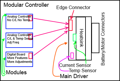
If we split the driver side and the high current section into seperate modules, It means we can add more features to the low current side while only adding the parts to the high current side that we will use. For example, as of this update we have a temp sensor on the board and a current sensor. If a customer orders a controller with these options we can just add a driver which is suitable for the customer that has these options build into the board. if a customer requires a simpler controller with none of these features then we don't need to add them. Not every customer needs Current Limiting (C/L) or temperature sensing or whatever other features we've added.
You can see by the diagram below what our current line of thinking is.
Update:
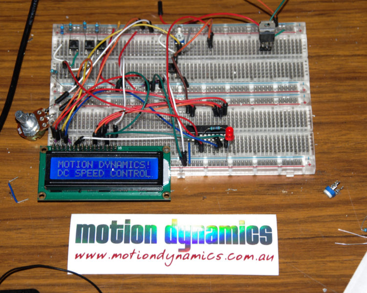
You can see part of a digital controller here (Below). It has progressed a lot with about 60% of the software programmed and part of the board laid out.
it hasn't been without hiccups though. I thought I was so clever implementing a check to see wether the LCD was connected or not. When it senses theres no LCD connected, it prints "NO LCD CONNECTED". Luckily nobody will ever see my mistake.
This is a LCD driver module with a menu setup and a full bridge driver. Being digital i can have a heap of features! It's likely this will come along after the first analog module.
I still have a way to go with this, but not a heap of time to dedicate to it. However, it IS progressing. The great thing about it is that if I want a feature i can just program it in!
I wish I'd chosen an 8k module instead of a 4kb module though. I'm forever optimising code to shave a few bytes here and there. I still can change it of course, but we'll see how we go!
After all, I may yet squeeze it all in!

With this model (insanity III) I am going to initially start with the basic model with the module and then build on from there. I'd like to get this one released asap.
There are many decisions I've been pondering in regards to this model. Basically, I'd like to stop using heatsinks like the current version has. Even though we offer it in a PCB version, it was never designed for this (no mounting holes!)
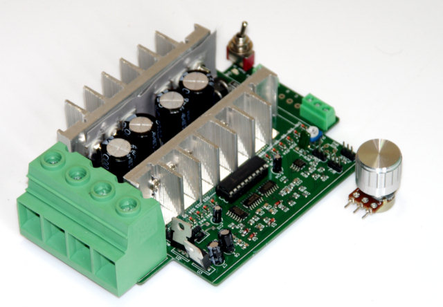
You can see the current board below. Visible are the power stages, the driver, the logic, the pwm generator, part of the high current drive system and a few other things.
This is actually one of the early boards where we made the heatsinks in one piece. In the later boards we cut one of the heatsinks in half so we didn't need to use the plastic insulators which despite being heat rated still managed to melt. You can see them on the model below.
To assemble one of these is horrible, I cringe every time I get an order for them, but despite that, it was probably one of my best designed boards to date. There were a lot of very happy customers and businesses that use this.
The new one will be very different!