Speed Controller Design
Speed control design
When it comes to speed controllers, there are just so many different types out there that it becomes difficult to make a decision on what's right for you. Some controllers are good, some are bad and some are just average. They'll do the job with the most basic of features. Lots of industrial customers prefer average! Why? Its simple! The less there is for customers to play with, the better!
One of the worst things about speed controllers in general is methods that businesses use to determine the controller current ratings. There are different ways that companies label their controller current capacity with most of them being either confusing, unrealistic or total fantasy and in no way achievable.
Manufacturers of RC car speed controllers seem to be the worst for ratings because they tend to use the label rating of the Mosfet which is always high but only ever achievable in circumstances that are impossible to happen outside a controlled lab environment. Lets take this IRF1405 N-Channel Mosfet as an example.
We used these for a while and we were really impressed with the robustness they possessed! Because they were so good and available in such high quantities, they were also cheao to buy!
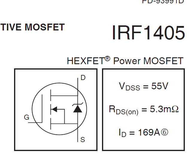
Looks good right? 169 Amps or pure awesomeness! Put 4 of them in parallel and you have 696 Amps of power!
Really blows you away when you look at it like that doesn't it? If I saw a 676 Amp controller for less that $100 I'd snap them up in a heartbeat and sell them! My customers would love me (maybe more so than they already do?)
Now, if we apply some practical common sense and look at things a little more critically, the first thing we notice is that there's no way that those thin Mosfet legs on a TO-220 case can carry 169 amps. So, as we read more of the datasheet, we can see that there's a small note that tells us that it's package limited to 75A, which means that those thin legs can really only carry a maximum or 75 real world amps. Bummer. Ok, well there goes our dream 696 amp controller. But now we still have a 300 Amp controller right? Well, kind of...
That current rating is assuming the best possible ambient operating conditions for the Mosfet. Which are certainly not the best conditions for you! However, the mosfet's ideal holiday destination would be somewhere in Antarctica, lounging arond on a heat sink, the size of a small bus. But for the rest of us, we know that's just unrealistic. Well, unless there's another ice age, in which case your 20 amp controller at home just became a 40 amp controller. Woohoo!!
So, how much for a single Mosfet?
without getting into the math and keeping everything really simple, also assuming we are talking about the same Mosfet as I have posted (1405) in real world conditions, I probably wouldn't pull anything more than 15% of the rated maximum.
So now in reality, using just a heatsink with no fan we have a 120 Amp controller. It will do about 80a-120a Amps continuously (dependent on the size heat sink) and up to 200A burst currents for short periods of time.
That's much closer to what real figures would be. For us, we'd likely derate it a little further and call it a 100A controller because you can't predict a customers usage and so its better to be on the safe side.
We generally don't like to advertise high burst rates, because some people will read that as the controller can do this awesome 200A burst, so it MUST be able to run this all day every day! I wish I was kidding when I say this.
Another way I've seen companies sell their controllers is to advertise them at their burst rates. For example, with our above controller they would advertise it something like this:
Brand Name Controller, 12v-24V 200A Super High Efficiency!
Peak current: 1 minute 200A
Continuous current: 120A
Does this look appealing to you ? If so, please tell me so I can change my advertising!
I'm not sure how I feel about this, it's not misleading or anything, but I guess just a little different and probably SEO friendly (search engine keywords) for people looking for bigger controllers.
Another misconception is the way H-Bridge controllers are rated. This seems to be a mixed bag and some experienced people will tell you it's rated one way, while others will tell you its the other way. I'm not sure why companies and businesses do this, but they do. So read this and decide for yourself.
Sorry for my lack or artistic talent, but you'll get over it.
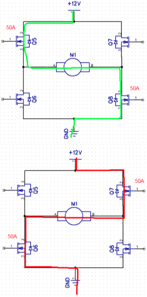
This is a basic H-Bridge. Now you can see where I've drawn the forward and reverse operations.
In this drawing there's 1 Mosfet per leg of the bridge. Now the way a H-bridge works is that any 2 of the 4 Mosfets will be active at any one time. Never all 4, and if all 4 are working at the same time then I guarantee your controller is burning and probably on fire, soon to be a smelly table ornament that you talk about with fellow nerds over alcohol free beers, as you describe the awesome fire, smoke and flames.
Anyway, I've labeled each Mosfet as 50 Amps peak. From what I've seen, some places that sell these would label this type of controller as a 100A reversible/bi-directional controller. And I guess if you want to be technical, it kind of is. You have 50A passing through the Mosfet at the top and 50A coming through through the Mosfet at the bottom. That means the motor is seeing 50A in both directions right? That's 100A!
Personally, I don't think so. I know I definitely wouldn't sell it as a 100A controller. I'd label it as a 50A controller. Why? Because the motor is only getting 50A through the upper Mosfet at the top and a 50A path to ground through the lower Mosfet. Yes, the Mosfets may be moving 100A, but in reality the motor will only ever see 50A.
I've seen this a few times, but only today a customer rang me and told me his 40A controller from another manufacturer was blowing up, and yet his current meter, showed the current draw as only 35A (5A under the controllers rated load). He couldn't understand what he was doing wrong, and the manufacturer told him it was definitely a 40A controller.
He sent me a picture of it and gave me the Mosfet details. His Mosfets were P and N channel, a 3205 and a 4905. One rated for -75A and one for 110A according to the datasheets. It was coupled with a heat sink. The heat sink I saw was probably a 1cm x 2cm 2mm thick piece of aluminum glued to the copper side of the PCB! It had 1 Mosfet per leg of the bridge!
Now, me personally, I wouldn't push them past about 15A in good conditions, but the maker assumed they would be good for 20A per Mosfet and then he used the above method to set the current capability of the controller. He's sells it happily as a 40A controller. And most people wouldn't know unless they actually pushed it to its supposed limit for a sustained time. I can guarantee it wouldn't handle 40A for any sustained amount of time.
The first because most people (from my experience) use common sense when they buy a controller. If they have a 25A motor they will buy a 50A controller. Its only the people that buy the 40A controller for a 35A rated motor who will notice because it will always be running the Mosfets close to the makers intended rating or even slightly above, which ultimately shortens the life and eventually it will cause problems.
The second, is because most motors will only peak at startup or stall (or under intense loads) so in general, unless you run a current meter along side your motor or load, you will never notice it.
Spending money on something that emits smoke and fire is great... if you buy fireworks, or maybe a flame thrower. It's probably not so much enjoyment if you just toasted an expensive controller.
If you buy a 50A controller for a 50A motor, then you are going to be fixing your controller regularly unless you motor is generally doing really light work. Why ? most motor makers only put the rated load on the label. This doesn't include startup currents or stall currents, which can be 2-3 times higher than the rated load. Also, if you overload the motor, the current draw can be much higher than the rated load, even though the motor appears to be working normally.
Then there's the 100% super duper genuine honest controllers (usually from China) that overrate their controllers capability. I don't know many (if any?) sellers that will offer any sort of warranty on these controllers as they tend to fail quite regularly (I know that we replace a lot of these). If you look at places like TNC, they clearly state that due to people wiring these incorrectly they cannot warrant them once they are opened from their sealed bags. Who can blame them? They know that the controller can be unreliable and prone to failure. Built cheap. But you can't tell people this, they seem to only hear what they want to hear, and if the label says 30A it *must* be true.
We brought some 30A controllers over from China at the insistence of a customer who had seen them for sale on eBay, Part of the term of sale was that we would not offer warranty of any kind. We explained to him that a 30 amp Chinese controller would be pushing to do anywhere near the stated current ratings for any extended periods of time except for on the motors they were initially designed for (which probably peak for short periods at 30A), but, he wouldn't listen. He was focused more on the cost and the extra chunk of profit he would make than the quality (hey, they were like $15-$17 each).
Anyway, after he blew up the first 3 running his 20 amp motor, he decided he was not so comfortable using these in his products. He sold the rest on eBay (and still made a profit).
But if you look at the feedback of these sellers you'll see the ones that actually bought a 30a controller for 25-30A applications will almost always have a failure and will complain about it. Its funny to read the feedback. The buyer calls it fraud, the Chinese seller claims they hooked it up wrong. Though if you keep looking you'll see quite a few of them obviously hooked the controllers up wrong. We advise people to de-rate them by 40%.
Talking to the customer today is what inspired me to write this all down. I don't think we've ever over rated a controller. I've sold them at their maximum current rating only (not burst rating) , but these days we tend to underrate them. Very few motors these days are true to label anyway and it adds a bit of a safety window for customers that don't know any different.
We do it because without you, we wouldn't be here, or is it because we care?, Maybe its because you are the most important aspect of our working lives?
More likely, its because we don't want to repair broken controllers. Repairing a few with new faults is ok because you see any weak points in the design that you didn't pick up before, but after that, who enjoys poking around with a scope trying to find that elusive fault? Win some, lose some, as long as the customer is happy.
Also, for our bi-directional speed controllers, we don't use P and N channel Mosfets, we only use N-channel. Why? N-channel Mosfets have much faster switching (RDS ON), are cheaper for higher current capability and a generally a lot more versatile than using a N and P channel setup. Also we can have less downtime between the Mosfet switching because the Mosfets don't have different opening and closing rates. Running N-channel is definitely more complex, but much more efficient.
Making small current controllers is easy, anybody can do it. There's literally hundreds of designs on the internet. Making larger current controllers is a little more difficult because you have so many factors to take into consideration. Theres also a lot of misinformation out there, so it's easy to get lost and do the wrong thing. If this is something that interests you, build all the designs you can and learn from all of them!